Una spira percorsa da corrente in un campo magnetico subisce un momento torcente: si comporta come una piccola calamita, un dipolo magnetico. Da qui nasce il motore elettrico. Questa sezione costruisce il momento magnetico (per N spire, N i A), il momento torcente e l’energia del dipolo, il funzionamento del motore con il commutatore e il bilancio energetico con la forza controelettromotrice, chiudendo con il solenoide.
Notazione: = momento magnetico, = momento torcente, = angolo tra e .
A current loop in a magnetic field experiences a torque: it behaves like a small magnet, a magnetic dipole. This is where the electric motor comes from. This section builds up the magnetic moment (for turns, ), the torque and energy of the dipole, how the motor works with its commutator, and the energy balance with the back electromotive force, ending with the solenoid.
Notation: = magnetic moment, = torque, = angle between and .
Abbiamo visto che un filo percorso da corrente in un campo magnetico subisce una forza. Se il filo forma una spira chiusa, le forze non la spostano: la fanno ruotare, proprio come succede all’ago di una bussola. Per descrivere questo comportamento basta un solo vettore, il momento magnetico.
Principio — Momento magnetico di una spira
Una spira chiusa di area percorsa da corrente ha un momento magnetico: dove è il versore normale alla spira, orientato secondo la regola della mano destra: le dita seguono la corrente, il pollice indica . Nel SI si misura in A·m².
Il momento magnetico riassume in un solo vettore tutto ciò che serve sapere della spira per prevederne il comportamento in un campo esterno: quanto è grande () e come è orientata ().
Per una bobina di spire sovrapposte il momento si moltiplica per : . Questa è la grandezza che compare in ogni formula di momento torcente ed energia del dipolo, ed è ciò che i costruttori massimizzano (tante spire, area grande, corrente elevata) per ottenere motori e strumenti sensibili.
Collegamenti
Argomenti: Magnetismo Concetti: Dipolo magnetico
Esercizi collegati: Momento torcente su una spira quadrata · Quale campo dà coppia massima · Motore e dinamo
We have seen that a current-carrying wire in a magnetic field feels a force. If the wire forms a closed loop, the forces do not move it along: they make it rotate, just like a compass needle. A single vector is enough to describe this behaviour: the magnetic moment.
Principle — Magnetic moment of a loop
A closed loop of area carrying current has a magnetic moment: where is the unit vector normal to the loop, oriented by the right-hand rule: the fingers follow the current, the thumb gives . In SI units is measured in A·m².
The magnetic moment packs into a single vector everything you need to know about the loop to predict how it behaves in an external field: how large it is () and how it is oriented ().
For a coil of stacked turns the moment is multiplied by : . This is the quantity that appears in every torque and energy formula for the dipole, and it is what designers maximise (many turns, large area, high current) to build motors and sensitive instruments.
Links
Topics: Magnetism Concepts: Magnetic dipole
Related exercises: Torque on a square loop · Which field gives maximum torque · Motor and dynamo
Immerso in un campo uniforme , un dipolo magnetico non viene traslato (le forze sui lati opposti della spira si bilanciano) ma ruotato: il campo tende ad allinearlo a sé.
Legge — Coppia ed energia di un dipolo magnetico
Per un dipolo in un campo uniforme :
Il modulo del momento torcente è , con angolo tra e : è massimo quando il dipolo è perpendicolare al campo, nullo quando è allineato. Nel SI si misura in A·m² e il momento torcente in N·m. L’energia potenziale è invece minima quando è parallelo a (equilibrio stabile) e massima quando è antiparallelo (equilibrio instabile).
Formula chiave
È lo stesso comportamento dell’ago di una bussola, che è a tutti gli effetti un dipolo magnetico: ruota finché il suo momento magnetico è allineato al campo terrestre: il polo nord dell’ago punta verso il Nord geografico (dove c’è un polo sud magnetico). Allo stesso modo la spira si comporta come un ago: la faccia da cui esce fa da polo nord. La tendenza all’allineamento, combinata con un meccanismo che inverte periodicamente la corrente, è ciò che rende possibile la rotazione continua di un motore elettrico.
Collegamenti
Argomenti: Magnetismo Concetti: Dipolo magnetico · Momento di una forza
Esercizi collegati: Momento torcente su una spira quadrata · Quale campo dà coppia massima · Esercizio svolto — spira rettangolare in campo uniforme
In a uniform field , a magnetic dipole is not pushed along (the forces on opposite sides of the loop cancel) but rotated: the field tends to line it up with itself.
Law — Torque and energy of a magnetic dipole
For a dipole in a uniform field :
The magnitude of the torque is , where is the angle between and : it is maximum when the dipole is perpendicular to the field and zero when it is aligned with it. In SI units is measured in A·m² and torque in N·m. The potential energy, on the other hand, is minimum when is parallel to (stable equilibrium) and maximum when it is antiparallel (unstable equilibrium).
Key formula
A compass needle behaves the same way, since it is a magnetic dipole in every respect: it rotates until its magnetic moment is aligned with the Earth’s field, so the needle’s north pole points to geographic North (where there is a magnetic south pole). A loop acts like a needle in the same way: the face from which emerges plays the role of the north pole. This tendency to align, combined with a mechanism that periodically reverses the current, is what makes the continuous rotation of an electric motor possible.
Links
Topics: Magnetism Concepts: Magnetic dipole · Moment of a force
Related exercises: Torque on a square loop · Which field gives maximum torque · Worked exercise — rectangular loop in a uniform field
Una spira percorsa da corrente in un campo magnetico subisce un momento torcente che tende a farla ruotare: è il cuore del motore elettrico, il dispositivo che converte energia elettrica in energia meccanica.
Storia — Dal filo di Faraday ai tram
L’idea del motore elettrico nasce nel 1821: Michael Faraday costruì il primo prototipo rudimentale, in cui un filo percorso da corrente girava intorno a un magnete immerso nel mercurio. Il primo motore pratico fu costruito nel 1834 da Moritz von Jacobi, ingegnere prussiano; nel 1838–39 un suo motore spinse una barca sul fiume Neva a San Pietroburgo. Oggi i motori elettrici muovono tutto, dai treni ad alta velocità agli hard disk al ventilatore dentro il PC.
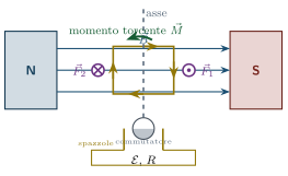
Motore elettrico elementare: spira tra due magneti permanenti, asse di rotazione verticale, commutatore a spazzole alimentato dal generatore. Le forze sui lati verticali sono perpendicolari al foglio (⊙ uscente, ⊗ entrante): formano una coppia che fa ruotare la spira attorno all’asse.
Analisi delle forze. Consideriamo una spira rettangolare di lati (paralleli all’asse) e (perpendicolari all’asse), percorsa da corrente in un campo uniforme . Ogni lato porta corrente in un campo, quindi sente :
- I due lati paralleli all’asse (lunghezza ) ricevono forze di verso opposto: formano una coppia che fa ruotare la spira.
- I due lati perpendicolari all’asse (lunghezza ) ricevono forze lungo l’asse, che si bilanciano e non producono rotazione.
Momento in funzione dell’angolo. Quando il piano della spira forma un angolo con , ciascun lato lungo agisce con un braccio , dove è l’angolo tra e . Il momento totale è:
dove è l’area della spira. Usando (qui ):
Legge — Momento torcente su una spira in campo magnetico
(per una sola spira N = 1) Il momento è massimo per (spira parallela a ) e nullo per (spira perpendicolare a , cioè allineato al campo).
Formula chiave — Motore elettrico
con = numero di spire.

Collegamenti
Argomenti: Magnetismo Concetti: Dipolo magnetico · Forza di Laplace · Momento di una forza
Esercizi collegati: Esercizio svolto — spira rettangolare in campo uniforme · Momento torcente su una spira quadrata · Quale campo dà coppia massima
A current loop in a magnetic field feels a torque that tends to make it rotate: this is the heart of the electric motor, the device that converts electrical energy into mechanical energy.
History — From Faraday's wire to trams
The idea of the electric motor dates back to 1821, when Michael Faraday built the first rudimentary prototype: a current-carrying wire that rotated around a magnet dipped in mercury. The first practical motor was built in 1834 by Moritz von Jacobi, a Prussian engineer; in 1838–39 one of his motors propelled a boat on the Neva river in Saint Petersburg. Today electric motors drive everything, from high-speed trains to hard disks to the fan inside your PC.
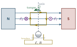
Elementary electric motor: a loop between two permanent magnets, vertical rotation axis, brush commutator fed by the generator. The forces on the vertical sides are perpendicular to the page (⊙ out of the page, ⊗ into the page): they form a couple that turns the loop about the axis.
Force analysis. Consider a rectangular loop with sides (parallel to the axis) and (perpendicular to the axis), carrying current in a uniform field . Each side carries current in a field, so it feels a force :
- The two sides parallel to the axis (length ) feel forces of magnitude in opposite directions: they form a couple that makes the loop rotate.
- The two sides perpendicular to the axis (length ) feel forces along the axis, which cancel and produce no rotation.
Torque as a function of angle. When the plane of the loop makes an angle with , each long side acts with a lever arm , where is the angle between and . The total torque is:
where is the area of the loop. Using (here ):
Law — Torque on a loop in a magnetic field
(for a single loop, ) The torque is maximum for (loop plane parallel to ) and zero for (loop plane perpendicular to , i.e. aligned with the field).
Key formula — Electric motor
with = number of turns.
Links
Topics: Magnetism Concepts: Magnetic dipole · Laplace force · Moment of a force
Related exercises: Worked exercise — rectangular loop in a uniform field · Torque on a square loop · Which field gives maximum torque
Se nulla intervenisse, la spira raggiungerebbe l’equilibrio (, parallelo a ): il momento torcente si annulla proprio lì, e la spira oscillerebbe attorno a quella posizione fino a fermarsi. Per avere una rotazione continua serve un trucco.
Il commutatore a spazzole inverte la corrente nella spira ogni mezza rotazione. Nella posizione di allineamento il momento è nullo, ma la spira ci arriva già in movimento e per inerzia la oltrepassa. Proprio in quell’istante il commutatore inverte la corrente: anche si inverte, e il momento torcente torna a spingere nello stesso senso di rotazione. Senza inversione, appena superato l’allineamento il momento frenerebbe la spira e la riporterebbe indietro.
Il meccanismo è semplice: il circuito della spira è collegato all’esterno tramite due semicilindri conduttori (semianelli) che ruotano con la spira, e due contatti fissi (spazzole) che strisciano su di essi. A ogni mezzo giro le spazzole passano da un semianello all’altro, invertendo il contatto e quindi il verso della corrente.
Un solo avvolgimento produce però un momento molto irregolare, che si annulla a ogni allineamento. Per avere un momento torcente più uniforme i motori reali usano più bobine sfasate e commutatori a molti segmenti: mentre una bobina passa per il punto morto, le altre sono in piena spinta, e il momento torcente risultante oscilla molto meno.
Collegamenti
Argomenti: Magnetismo Concetti: Dipolo magnetico
Esercizi collegati: Momento torcente su una spira quadrata · Quale campo dà coppia massima · Motore e dinamo
If nothing intervened, the loop would reach equilibrium (, parallel to ): the torque vanishes exactly there, and the loop would oscillate about that position until it stopped. Getting continuous rotation takes a trick.
The brush commutator reverses the current in the loop every half turn. At the aligned position the torque is zero, but the loop arrives there already moving and coasts past it by inertia. At exactly that moment the commutator reverses the current: reverses too, and the torque pushes again in the same sense of rotation. Without the reversal, as soon as the loop passed alignment the torque would brake it and pull it back.
The mechanism is simple: the loop’s circuit is connected to the outside through two conducting half-cylinders (split rings) that rotate with the loop, and two fixed contacts (brushes) that slide on them. Every half turn the brushes pass from one half-ring to the other, swapping the contacts and so reversing the current.
A single winding, however, gives a very uneven torque that drops to zero at every alignment. To get a smoother torque, real motors use several coils set at different angles and multi-segment commutators: while one coil passes through its dead point, the others are pushing at full strength, and the resulting torque fluctuates much less.
Links
Topics: Magnetism Concepts: Magnetic dipole
Related exercises: Torque on a square loop · Which field gives maximum torque · Motor and dynamo
Quando la spira ruota nel campo magnetico, il flusso attraverso di essa varia: per la legge di Faraday (prossimo capitolo) si genera una forza elettromotrice indotta che, per la legge di Lenz, si oppone alla corrente imposta. È la forza controelettromotrice (f.c.e.m.) del motore, indicata con .
In un circuito con generatore , resistenza totale e f.c.e.m. , vale
Più il motore gira veloce, più cresce e più la corrente assorbita diminuisce. Moltiplicando per entrambi i membri di si ottiene il bilancio delle potenze: la potenza elettrica in ingresso si ripartisce tra dissipazione Joule e potenza meccanica utile.
Principio — Bilancio energetico del motore
Il rendimento è .
Il risultato ha una conseguenza pratica importante: a motore fermo (, quindi ) tutta la potenza elettrica viene dissipata in calore, e la corrente assorbita è massima (). È il momento di maggior rischio di surriscaldamento: un motore bloccato meccanicamente, ma ancora alimentato, può bruciarsi.
Collegamenti
Argomenti: Magnetismo Concetti: Dipolo magnetico · Forza elettromotrice · Effetto Joule
Esercizi collegati: Esercizio svolto — motore elettrico sotto carico · Motore e dinamo · Dinamo a bicicletta
When the loop rotates in the magnetic field, the flux through it changes: by Faraday’s law (next chapter) an induced electromotive force appears which, by Lenz’s law, opposes the applied current. This is the motor’s back electromotive force (back emf), written .
In a circuit with generator , total resistance and back emf :
The faster the motor spins, the larger becomes and the smaller the current it draws. Multiplying both sides of by gives the power balance: the electrical input power splits into Joule dissipation and useful mechanical power.
Principle — Energy balance of the motor
The efficiency is .
This result has an important practical consequence: with the motor stalled (, so ) all the electrical power is turned into heat, and the current drawn is at its maximum (). This is when the risk of overheating is greatest: a motor that is mechanically jammed but still powered can burn out.
Links
Topics: Magnetism Concepts: Magnetic dipole · Electromotive force · Joule effect
Related exercises: Worked exercise — electric motor under load · Motor and dynamo · Bicycle dynamo
Un solenoide è una serie di spire impilate, tutte percorse dalla stessa corrente. Il suo effetto magnetico è quello di una lunga calamita cilindrica: concentra un campo intenso e uniforme al suo interno, quasi nullo all’esterno.
Ogni spira è un piccolo dipolo; mettendone N in fila, i momenti si sommano e il solenoide si comporta come una calamita a barra, con un polo nord all’estremità da cui escono le linee di .
Legge — Campo di un solenoide ideale
Dentro un solenoide di spire, lunghezza , percorso da corrente , il campo è uniforme e parallelo all’asse: All’esterno, .
Compare il rapporto , il numero di spire per unità di lunghezza: il campo dipende solo dalla densità di avvolgimento e dalla corrente, non dal diametro del solenoide.
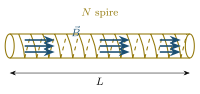
Solenoide ideale: campo uniforme e parallelo all’asse all’interno, praticamente nullo fuori.
Analogia
Il solenoide è l’analogo magnetico del condensatore piano: genera al suo interno un campo uniforme (come il condensatore genera un uniforme) e quasi nullo all’esterno.
Il verso di : la regola dell’autostop. La formula dà il modulo, non il verso. Il verso dipende da come è avvolto il filo e in che senso scorre la corrente: invertendo la corrente si inverte . Il modo più affidabile per determinarlo è la regola dell’autostop: si avvolgono le quattro dita della mano destra attorno al solenoide, chiuse a pugno, nello stesso verso in cui scorre la corrente nelle spire; il pollice esteso, come quello di un autostoppista, indica il verso del campo all’interno.
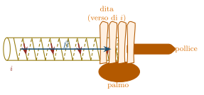
Regola dell’autostop: dita destre arrotolate nel verso della corrente, pollice lungo dentro il solenoide.
Sempre mano destra
La regola vale sempre con la mano destra. Usando la sinistra si ottiene il verso opposto e si sbaglia di sicuro. Si può usare anche al contrario: noto il verso di (per esempio con una bussola), si dispone il pollice destro in quel verso e le dita mostrano il senso in cui scorre la corrente.
Collegamenti
Argomenti: Magnetismo Concetti: Campo magnetico · Teorema di Ampère Competenze: Regola della mano destra
Esercizi collegati: Verifica dimensionale del campo del solenoide · Campo dentro un solenoide · Problema — Campo B nel condensatore in carica
A solenoid is a series of stacked loops, all carrying the same current. Magnetically it acts like a long cylindrical magnet: it concentrates a strong, uniform field inside and almost none outside.
Each turn is a small dipole; lining up of them, their moments add up and the solenoid behaves like a bar magnet, with a north pole at the end from which the lines of emerge.
Law — Field of an ideal solenoid
Inside a solenoid of turns and length carrying current , the field is uniform and parallel to the axis: Outside, .
The ratio , the number of turns per unit length, appears here: the field depends only on how densely the wire is wound and on the current, not on the diameter of the solenoid.
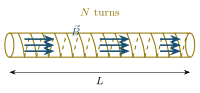
Ideal solenoid: uniform field parallel to the axis inside, practically zero outside.
Analogy
The solenoid is the magnetic counterpart of the parallel-plate capacitor: it produces a uniform field inside (just as the capacitor produces a uniform ) and almost no field outside.
The direction of : the right-hand grip rule. The formula gives the magnitude, not the direction. The direction depends on how the wire is wound and which way the current flows: reversing the current reverses . The most reliable way to find it is the right-hand grip rule: curl the four fingers of your right hand around the solenoid, as in a fist, in the direction the current flows in the turns; your outstretched thumb, like a hitchhiker’s, points in the direction of inside.
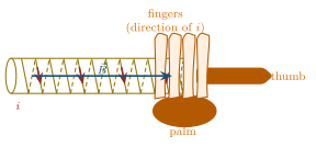
Hitchhiker’s rule: right-hand fingers curled in the direction of the current, thumb along inside the solenoid.
Always the right hand
The rule always uses the right hand. With the left hand you get the opposite direction, which is always wrong. It also works in reverse: if you know the direction of (for example from a compass), point your right thumb that way and your fingers show which way the current flows.
Links
Topics: Magnetism Concepts: Magnetic field · Ampère’s law Skills: Right-hand rule
Related exercises: Dimensional check of the solenoid field · Field inside a solenoid · Problem — B field in a charging capacitor